Search Results
8 items found for ""
- Effect of ERV on AC Run Time
My colleague and I had a recent discussion about his ongoing project. We focused on figuring out how adding an Energy Recovery Ventilator (ERV) to treat ventilation air impacts the run time of air conditioning equipment. To answer this, we used adicot.com's Psychrometric Chart 2-Condition Calclator and the methodology shown below to compare equipment run times with untreated ventilation air versus ventilation air treated by an ERV. The results showed an impressive 27% reduction in equipment run time due to the ERV implementation. You'll find the details of our approach in the following section. To solve this problem, we assumed the following will be given: Given: Equipment Cooling Capacity [BTU/h] provided by the manufacturer ASHRAE Outside air design temperatures (Dry bulb and wet bulb) [oF] Coil Leaving Air Temperatures (Dry bulb and wet bulb) [oF] provided by the manufacturer Ventilation air volume [cfm] per ASHRAE 62.# or Building Code Procedure: Calculate the Ventilation Air Total Cooling Load [BTU/h] (Psychrometric Chart 2-Condition Calculator) Run time = Ventilation load/Equipment Capacity x 60 min [min] Example: Equipment Cooling Capacity: 2.50 tons or 30,000 BTU/h Outside air temperatures in Boston, MA: 88oF / 72oF Coil Leaving Air Temperatures: 55oF / 54.9oF Ventilation air volume: 100 CFM Calculate the total load of ventilation air using Psychrometric Chart 2-Condition Calculator where: Entering Conditions are outside air design temperatures Exiting Conditions are coil-leaving air temperatures Ventilation Air Total Cooling Load = 5,483 BTU/h Run time =5,483 BTU/h / 30,000 BTU/h x 60 min/hr = 11 minutes/hour to condition the ventilation air Adding an ERV: Replace outside air temperature with the ERV leaving air temperature (100 CFM @ 78 Dry bulb, 68 Wet bulb): Total Load: 4,023 BTU/h Run time: 8 minutes/hour to condition ventilation air The results show the effect of ERV or AC Equipment Run time is significant and that adding an ERV reduces the equipment run time caused by ventilation air by 27%. Let us know how you use our Adicot Calculators
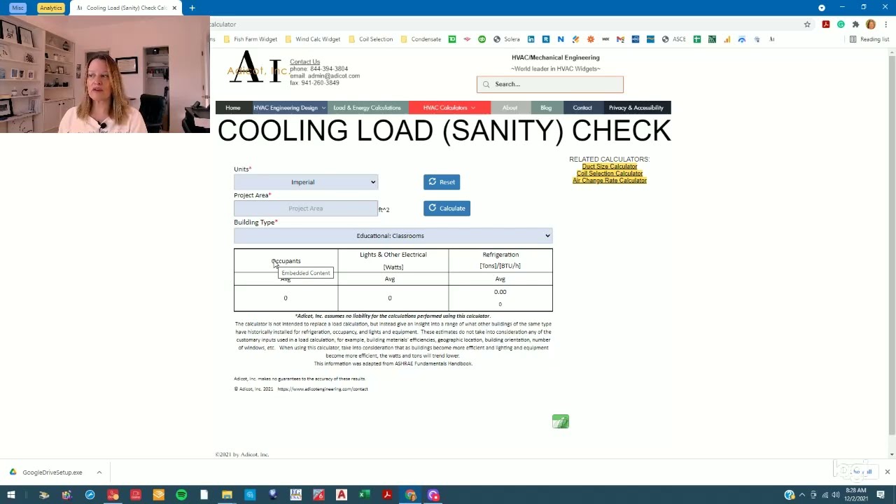
- How to Use the Cooling Load (Sanity) Check Calculator
This video shows How to use the Cooling Load (Sanity) Check Calculator. You can access all our calc ulators on the HVAC Calculators page. This Cooling Load Sanity Check Calculator is a valuable tool for architects, engineers, building owners, and developers to use in pre-design meetings and during the design phase as a "sanity check" for your load calculation. As a caveat, the calculator is not intended to replace a load calculation. Instead, it gives an insight into the range of what other buildings of the same type have historically installed for refrigera tion, occupancy, and lights and equipment. These estimates do not consider any of the standard inputs used in a load calculation, for example, building materials' efficiencies, geographic location, building orientation, and the number of windows. When using this calculator, consider that as buildings become more efficient and lighting and equipment become more efficient, the watts and tons will trend lower. A quick example of How to use the Cooling Load (Sanity) Check Calculator: as with most of our calculators, you can choose Imperial or Metric units. Let's demonstrate this calculator using Imperial units. We will evaluate a 10,000 SF (929 m^2) office space. The data for this calculator was gathered from various sources , and the output informat ion may look different depending on the Building Type you select. Select Imperial Units from the Units dropdown menu, enter 10,000 SF in the Project Area box, and select Office: One Story from the Building Type dropdown menu. The result is an estimated 29 tons of cooling. You can play around with the building type to gain more information about the range of refrigeration you might expect. Let's select Office: Office Buildings (General). The results now show a capacity of 28-tons to 53-tons. You can discern whether your building will be on the high end or low end of this estimate based on things like orientation, location, and quality of construction.
- Vapor Pressure Deficit (VPD) Calculator
This article and video provide a demonstration of Adicot's Vapor Pressure Deficit (VPD) Calculator for Indoor Growers and Grow Rooms. This calculator is a useful tool for Indoor Growers setting up Grow Rooms. The user is able to hone in on temperature and humidity values to optimize plant health as well as energy conservation. This Vapor Pressure Deficit (VPD) calculator is used to determine temperature and humidity for indoor grow rooms. I am not a grower, so I cannot advise you what your VPD should be, but here is an excellent article From Cannabis Science and Technology describing VPD at different stages of growth. So let us get right into it. You can choose either imperial or metric units. For this demonstration, I will use imperial units. Begin by entering room conditions of 78 degrees Fahrenheit and 60% relative humidity. When you hover over the Leaf Temperature input box, a note explains that as the leaf grows, more evaporative cooling takes place, so the leaf temperature drops. If you do not know your leaf temperature, a rule of thumb is that you could assume a temperature drop of about 2 degrees Fahrenheit. Following that rule of thumb, we will use a leaf temperature of 76 degrees Fahrenheit. These inputs give a room VPD of 1.31kPa and a leaf VPD of 1.1kPa. The clear benefit of targeting a VPD is healthy, robust plants. Another benefit of targeting VPD is energy savings. Let us try one more scenario. Let us say you are in a hot, humid climate. You can allow the temperature to be set to 82 degrees Fahrenheit and 65% relative humidity and still achieve the same leaf and room VPD values of 1.31kPa and 1.1KPa, respectively.
- How to use the Commercial Kitchen Exhaust Hood Calculator
This article demonstrates the use of the Commercial Kitchen Exhaust Hood Calculator. You can access all calculators on the HVAC Calculators page or by the dropdown menu. The calculators are listed alphabetically by category. There is a list of instructions at the top of the calculator and a note explaining that a separate analysis needs to be done for each hood. So let's get started. This demonstration is based on a project I am currently working on. It is in the US, so we will select English Units. The client specified a Wall Mounted Canopy, so we will choose this from the dropdown list. If you hover over the dropdown list, there is a description/summary from ASHRAE of the differences between the hoods. Let's call the Project Name Demonstration Kitchen and designate this exhaust hood as KEF-1. If you hover over the Hood Type dropdown list, there is a description of the hood types. Our application will be a Type I hood. The client provided a kitchen layout with the following equipment under the hood: 30" Range, hot top, gas 36" Griddle, flat, gas 48" Fryer, open deep-fat, gas The equipment is listed alphabetically. Select the equipment type from the list and enter linear inches of equipment. To add another piece of equipment under the hood, check the "Other Equipment" box. Enter all of the equipment. After the equipment has been entered, there is one more optional input. If the design also includes a Make-Up Air Unit, enter the percentage of Make-up air in the dropdown box in the Summary Table. The summary table gives the linear feet of equipment and subsequent required linear feet of the hood. The Exhaust rate per the 2018 International Mechanical Code and the exhaust rate range per ASHRAE and their relevant make-up air volumes if applicable. Based on your inputs, there are also some notes from ASHRAE, the Florida Building Code, and the International Mechanical Code. Back to the project, this is a small restaurant, and the most significant load is the outdoor air required to keep the building in balance. The restaurant owner decided to reconfigure the kitchen and switch to a Single Island Canopy. I advised my client that changing hoods would increase the required hood flow rate (and make-up air) from 3,150 CFM to 5,250 CFM and was not practical based on their restaurant's space constraints and budget.
- How to Use the Duct Size Calculator / Ductulator
This video shows how to use the online Duct Size Calculator / Ductulator. You can access all our calculators on the HVAC Calculators page or by the dropdown menu. The calculators are listed alphabetically by category. We can choose to design with Flex, Metal or Duct board. For this example, let's choose Duct Board from the material dropdown menu. All calculations require you to enter the volume flow rate, so let's use 265 cfm. Now we need to enter one more input. We can enter air velocity, friction loss, duct diameter, or rectangular duct dimensions. For this example, we will select friction loss and set it to 0.1in. w.g./100'. Let's also add the constraint that the outer duct height cannot be greater than 9". We are using standard R-6 duct board, which has a thickness of 1.5". Therefore, our inner duct height, has to be 6" (9" outer dimension minus 3" for insulation). Enter 6" into the Duct Height (Optional) field. The results table show a 10"x6" duct. This calculator can also be used to simply convert round to rectangular or vice versa. It is unnecessary to consider the duct material, length, or air volume since it is just a physical, geometric calculation. Assume we have an 18" round duct. We can see the equivalent rec duct is 16"x16". Next, let's assume we also have an inner height constraint of 10", the equivalent rectangular duct would be 26"x10".
- Collecting Building Info for Load and Energy Calcs
At Adicot, Inc. we collect the building information we need to complete our work using an internal Work Order; however, we are on the perpetual hunt to gather that information; and in the process, we have two main goals, accuracy, and to make the process as easy as possible for our clients. This article focuses on Collecting Building Info for Load and Energy Calcs. We start the work order process by reviewing all documentation provided by our clients, reviewing the exterior of the building in Google Maps, and researching the applicable property appraiser's website. Sometimes we still need more information. A recent project was an example of one which we still needed more information, and we felt that our client's method was so thorough, clear, and concise, that we wanted to share as a "best practice". We presented the client with a bulleted list of information still needed to proceed with the project and he responded with a three-page document addressing each bullet point. The beauty in the response is the layout on page 3. He provided some of the information directly on the layout, but then used a system symbols, letters, and numbers to link additional information. We appreciated this client's efforts very much, and this clear, comprehensive delivery of information allowed us to work more efficiently and reduced the risk of mistakes. We are lucky at Adicot to have such amazing clients! Thank you for making the process as easy as possible for us! #Load #Energycalculations #hvacloadcalculations #loadenergydesign #workorder #hvacengineering #hvac #ductlayout #acloadcalculation
- Heat Load Calculations - Baseline vs High Efficiency
Adicot is working on a project for One Community, a non-profit creating open source plans and designs for sustainable cities and homes. The specific project we are working on is assisting in their HVAC Design of their mixed use City Center. The City Center has a few unique characteristics; a root cellar, server rooms, an indoor pool... oh, and it is comprised of three geodesic domes. The One Community designers have chosen an R-45 insulation for the exterior surfaces of the domes. With building insulation, equipment loads, and people loads remaining constant, two heat load calculations were performed; a baseline load using International Energy Code minimums and ASHRAE Fundamentals default materials, and a high efficiency (HE) version of the city center. The HE version included the following changes: It is worth mentioning the benefits outlined below are just analyzing the effect on the heating and cooling systems; but the benefits to building efficiently have much farther reaching benefits. One example is switching to LED lighting from regular incandescent lighting. Incandescent bulbs put off more heat than LED bulbs. THis heat is a form of wasted energy which causes increased demand on the cooling system in the summer. By switching to LED bulbs, the reduced heat load to the building means lower cooling costs in the summer, means smaller capacity cooling system; also, the bulbs lower power consumption means less energy, which all means a more comfortable building powered by a smaller array of photovoltaic panels. Building Construction A tighter building means greater temperature control. One Community's City Center prototype building will be in Southern Utah. The domes are designed for passive cooling during the summer months with backup air conditioning for extreme temperature periods. The winter lows in Southern Utah can dip into the single digits, so during the winter, to avoid drafts, efficiently maintain comfortable temperatures, and maintain proper building air balance, a tightly constructed building is an even more critical consideration. Building air tightness is improved by sealing leakage pathways; e.g., ensuring windows and doors are properly installed with weather stripping, sealants, gaskets, etc., and outlets and recessed lights, which often make easy pathways between conditioned and non-conditioned spaces, must be sealed. A source for more information on this is found on in the Building Technologies Program Air Leakage Guide by the US Department of Energy. Below are the results of One Community's City Center prototype building in Southern Utah comparing an "average building" (a maximum of 0.17 air changes per hour(ACH) in the summer and 0.32 ACH in the winter) to a "tight building" (a maximum of 0.6 ACH in the summer and 0.12 ACH in the winter). Properly sealing the building makes a significant impact on the results of the heating load calculation. It cut's the impact of outside air infiltration by over 50% for all spaces of the building. Ventilation A tight building also comes along with requirement for greater attention to ventilation to ensure the comfort and health of the occupants. Two options when introducing ventilation air into a building are considered for this analysis. The Baseline method is modeled such that the fresh air directly enters the air handling unit's return; the High Efficiency method is modeled such that the outdoor air is pre-treated to 63 degree fahrenheit, before being introducing it into the air handler. The impact on the heating load is below: It is not surprising that the burden on the primary heating system is significantly reduced when 63 degree air is introduced versus 8 degree air. What is not represented here is the energy and equipment needed to pretreat the air to 63 degree. A dedicated outdoor air system (DOAS) has been recommended as it is specifically designed for this functionality. A DOAS will have additional upfront, maintenance and operating costs, so this delta is not all savings. A further more in depth analysis will b e discussed in a follow up blog entry. Fenestration In comparison to some geodesic domes, the glass to wall ratio on this structure is well balanced; this is a sound design choice when optimizing for energy efficiency. The International Energy Code Table C303.1.3 lists default values for window specifications given their physical characteristics. The Baseline building was modeled using metal frame, clear, double glazed fenestration (U=0.8, SHGC=0.7). Since the time of this writing, exact windows have not been specified, Efficient Windows Collaborative's window selection tool was used to select windows with the following U=0.22 and SHGC=0.25. As expected, more efficient windows greatly reduce the heat loss of the building to the outdoors. Lighting The final variable used in the Baseline vs High Efficiency building comparison is lighting. As stated earlier, there are a multitude of benefits over and above HVAC equipment sizing when selecting more energy efficient light bulbs. You can read more about this at One Community's Lighting Analysis. Since lighting adds heat to the building, inefficiency in lighting burdens the HVAC systems during building cooling. Below is a comparison on the energy usage for cooling with baseline lighting as dictated in ASHRAE Fundamentals Chapter 18 Table 2 for the various spaces versus the high efficiency building which uses low wattage high efficiency bulbs: The graph displays a significant savings for the cooling load by using LED low wattage bulbs versus traditional ASHRAE design standards. So which do I recommend they implement? ALL design changes are highly recommended. It is not possible to emphasize enough the benefits to all three pillars of sustainability, people, planet and profits. Which has the greatest impact to equipment sizing? The charts below give a representation of the burden each factor places on the system. It is clear that tempering the outside air* is absolutely necessary (and most likely dictated by local building codes); but all factors show measurable and viable improvements: *All data regarding ventilation will be addressed in an upcoming blog post, and the charts above will be updated to reflect the additional analysis incorporating a Dedicated Outdoor Air System (DOAS). #loadcalculation #heatloadcalc #coolingloadcalc #highefficiency #Adicot #mechanicalengineering #heatingloaddetails #MechanicalEngineering #HVACEngineering #hvac #hvacload #heatloadcalculation #heatloadcalculations #coolingloadcalculation #coolingloadcalculations #loadcalc #loadcalculations
- AutoCAD Tips & Cheats
As a self-taught AutoCAD user, I learn everything by either stumbling upon something wonderful, or extensive research to find the solution to an obstacle. Since AutoCAD's capabilities are so vast, and finding solutions to problems can be an arduous task, I often write down obscure solutions (obscure to someone self-taught at least) which I will not use often enough to commit to memory but do not want to have to research again. We are going hi-tech at Adicot! Since my cheat sheet is getting full and not conducive to sharing, I have included my favorite AutoCAD Tips & Cheats. If you have any great AutoCAD tips, please share in the comments! Using the keyboard to enter commands instead of icons is much more efficient. Here is an extensive list of shortcuts: http://www.autodesk.com/store/autocad-shortcuts# But instead of trying to memorize short cuts, think about what you want to do and begin typing. Example: You want to hatch an area. You could try to memorize which on ribbon the Hatch is located, or just start typing Hatch, and AutoCAD will give you list of options. Select H (HATCH) from that list. If you use HATCH frequently enough that it is worth committing to memory, AutoCAD has provided you the shortcut, H(HATCH); so next time type H at the command line and press Enter. Example: I can never remember how to isolate a layer; is it ISOLAY, or LAYISO? It doesn’t matter, just start typing and AutoCAD will populate the list of possible options. In this case, I started typing ISO and LAYISO popped up. Select LAYISO from the list. (Isolating a layer locks all other layers except the one selected, LAYUNISO, restores all layers to their previous state) If you do not immediately see the command you expected, the window that pops up is scrollable. See if the command you are looking for is further down the list. This is also a good way to learn new commands since AutoCAD populates a list of commands using the letters you enter. Always with efficiency in mind, some commands you will just want to memorize. In almost every case I prefer to use MTEXT rather than TEXT because it is much more editable. How convenient that the command for MTEXT is simply T. Type T at the command line and press enter and you will begin creating an MTEXT object. Some commands that I use all the time or that took me forever to figure out once and that I never wanted to have to figure out again: CO: C(OPY) This works differently from the standard shortcut of Ctrl+C. COPY can only copy to the same drawing but will make multiple copies. Ctrl+C can copy to the same drawing or any other drawing file, but needs the Ctrl+V command to paste. Q: Q(SAVE) the drawing (SAVE is actually Save As where you can change the filename and the file location) DIMSCALE: I always set DIMSCALE when starting a new drawing based on the following: http://www.designmaster.biz/support/QandA/HowtoSetDIMSCALE.html This can help adjust size of text, leaderhead arrows, and other drawing elements. LTSCALE: It is also a good idea to set LTSCALE using the same scale as DIMSCALE. I discovered LTSCALE when the “hidden” line type was not visible because LTSCALE was set too low. Sometimes in an active drawing Z(OOM) > E(XTENTS), results in a blank screen with a small dot in the center. To get rid of this: Z(OOM) E(XTENTS) ERASE ALL R(EMOVE) Drag a window around the dot in the middle of the screen Enter Now try Z(OOM) > E(XTENTS) again and the drawing should be as expected, rather than a small dot in the center of a black screen. TXT2MTXT - Converts TEXT to MTEXT MIRRTEXT 0: Will NOT mirror text 1: Will mirror text PDFOSNAP 1: Will allow you to snap to objects in a pdf External Reference (XREF) object IMAGEFRAME, PDFFRAME, DWFFRAME, DNGFRAME, XCLIPFRAME 0: Not visible, not printed 1: Visible and plots 2: Displays by does not print 3: Various LAYFRZ: Freeze layer in a viewport - select the viewport for which you want this layer to be frozen VPMAX: Expands the current layout viewport for editing VPMIN: Restores the current layout viewport Snap To Menu Shortcut: Ctrl + RightClick brings up the snap to menu, either click the snap type you need or in many instances, typ the first letter snap type. Examples: E - Endpoint M- Midpoint P- Perpendicular R- Near C- Center PURGE: Removes unused items, such as block definitions and layers, from the drawing LAYMRG: merges selected layers into a target layer; the layer you select to merge into the target layer is delete QSELECT: Creates a selection set based on filtering criteria (Example: Select all text of a particular style) The Up Arrow scrolls through previously used commands at the command line. Once you get to the command you were looking for, press the Enter key start that command. Enter repeats the last command FIELDEVAL: Decide when to update field values At the Command prompt, enter fieldeval. Enter a bitcode that is the sum of any of the following values: For example, to update fields only when the file is opened, saved, or plotted, enter 7 0: Not updated 1: Updated on open 2:Updated on save 4:Updated on plot 8:Updated on use of ETRANSMIT 16: Updated on regeneration For example, to update fields only when the file is opened, saved, or plotted, enter 7. To update field when any action from the above list occurs, enter 31. FIND: Find (and Replace) Text in the File: At the command prompt, enter FIND to pull up the Find and Replace Dialog Box. NUMBERING SHEETS: Use the Tab Name to Automatically Set the Sheet Name From a layout tab, create a textbox where the sheet name/number should go. Click on the Field Icon in the Text Editor ribbon and select: Field Category: Other Field Names: SystemVariable System variable: ctab Format: Choose applicable options #autocad #tips #cad #drafting #mtext #mechanicalengineer